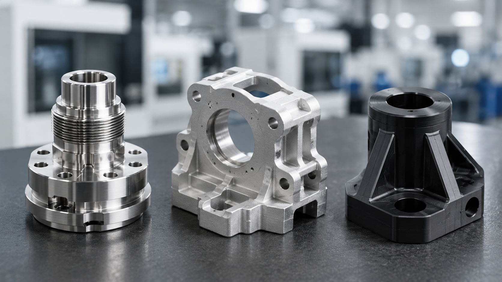
Getting custom parts made can be frustrating. You send your design, but the final product is wrong. This wastes time and money, and your project stalls.
CAM software is the key. It translates your 3D model into instructions a CNC machine understands.1 A skilled supplier uses it to optimize toolpaths, ensure accuracy, and speed up production2, turning your complex design into a perfect physical part.
You might be thinking, "That sounds great, but how does this actually help me?" It's not just about owning the software. It's about how the supplier uses it. The questions you ask a potential partner can reveal if they truly understand how to make your parts right. Let's look at what you need to ask to find a true manufacturing partner, not just a machine shop.
How Should Your Supplier Handle Design for Manufacturability (DFM)?
You finalized your design, but is it ready for manufacturing? Hidden issues can cause delays and cost increases, a frustrating surprise you do not need.
A good supplier uses CAM software for a thorough DFM review. They analyze your 3D model to spot potential problems like thin walls or difficult features before any metal is cut.3 This saves you significant time and money.4
DFM is more than just finding mistakes. It is a partnership. Before we start any job, we load your 3D model into our CAM system. This lets us run a complete virtual simulation of the machining process.5 We are not just looking for errors. We are looking for opportunities to make your part better, stronger, and more cost-effective. I remember a client who designed a complex aluminum housing. The design looked fine, but our DFM simulation showed that a deep pocket would cause tool vibration. This would lead to a poor surface finish. We suggested adding a small radius to the corner. This simple change did not affect the part's function, but it allowed us to use a stronger tool and machine the part perfectly. The client was happy we found this before we wasted any material. It is this kind of proactive analysis that separates a good supplier from a great one.
| DFM Check | Purpose | Impact if Missed |
|---|---|---|
| Wall Thickness | Ensures the part is strong enough. | The part could warp during machining or break in use.6 |
| Tool Accessibility | Checks if our tools can reach every surface. | Some features may be impossible to machine as designed. |
| Internal Radii | Matches corner radii to standard tool sizes. | Mismatched radii require special tools and increase costs.7 |
| Material Choice | Confirms the design is suitable for the chosen material. | The part may be difficult to machine or fail to perform. |
What Should You Ask About Their CAM Programming Strategy?
Your part might look simple, but the wrong machining strategy can ruin it. A cheap quote could hide an inefficient method that leads to poor quality and missed deadlines.
Ask your supplier how their CAM strategy optimizes for quality, speed, and cost. A good partner will explain their choice of toolpaths and cutting parameters to ensure your parts are made efficiently and correctly the first time.
A CAM programming strategy is a plan for how we will cut your part. It is not just about pushing a button. Our programmers are like master chefs, and the toolpaths are their recipes. They have to balance many things: speed, surface finish, tool life, and part accuracy. For example, we often use a strategy called "adaptive clearing" for roughing out material. Instead of old-school pocketing, this toolpath maintains a constant, light engagement with the material. This lets the machine run much faster and puts less stress on the tool.8 I recall a project for a customer who needed a batch of heat sinks quickly. Our programmer chose an adaptive clearing strategy in our CAM software. We were able to run the machine at its maximum capability, which cut the cycle time nearly in half. The customer got their parts two days early. The magic was not in the machine, but in the intelligence of the CAM strategy. We always simulate the entire program to make sure it is perfect before we press "cycle start" on the real machine.
How Do They Machine Complex Features and Tight Tolerances?
Your design has intricate details and tight tolerances that are critical. You worry that a supplier might not be able to achieve the precision you need for your part to function.
A top-tier supplier uses advanced CAM software and multi-axis CNC machines to handle complexity. Their programmers create precise toolpaths for features like undercuts, curved surfaces, and thin walls, verifying everything through simulation.
Complex parts require more than just a good machine. They require a smart process, and that process is born in the CAM system. This is especially true for 5-axis machining. A 5-axis machine can move the tool and the part at the same time in complex ways.9 The CAM software is the brain that calculates every single one of these movements. It allows us to use shorter, more rigid tools and machine parts in a single setup, which greatly improves accuracy.10 A medical device company brought us a titanium bone implant. It had organic, curved surfaces and a tolerance of just ±0.005mm. Other shops told them it was impossible. Our team used our 5-axis CAM module to program a "swarf" toolpath. This strategy uses the side of the cutting tool to machine the entire curved surface in one smooth pass. The result was a flawless finish that met their strict medical standards.
| Complex Feature | CAM Solution | Machine Requirement |
|---|---|---|
| Undercuts | Specific toolpaths for lollipop or T-slot cutters. | 3-axis with special tools, or 5-axis machine. |
| Blended Surfaces | 3D surfacing toolpaths like "Scallop" or "Flowline". | 3, 4, or 5-axis machine. |
| Thin Walls | Controlled roughing and alternating finishing passes. | High-speed machine with precise feedback control. |
| Small Engraving | Engraving toolpaths with fine step-over control. | High-RPM spindle and precise machine motion. |
What's Their Approach to Workholding and Clamping?
You probably don't think about how a part is held, but it's critical. Poor clamping can cause vibration, bad finishes, and inaccurate parts11, ruining your whole order.
A skilled supplier plans their workholding strategy within the CAM software. They design custom fixtures or choose optimal vise setups to ensure the part is rigid and accessible, simulating the setup to prevent collisions.
How we hold your part is one of the first things we think about. It is not an afterthought. A bad workholding strategy can ruin a good part. We plan our entire clamping setup directly in the CAM software. We can import models of our vises, clamps, and fixtures. This gives us a complete virtual picture of the machine, the part, the tools, and the workholding. We can then run a simulation to check for any potential collisions. It ensures our tool will not crash into a clamp halfway through the program. I remember a job for a thin electronics enclosure. If we held it in a normal vise and squeezed it, the part would have bowed like a potato chip. So, our engineering team designed a custom vacuum plate fixture. They modeled the fixture and imported it into the CAM program. We could then program all the toolpaths around the fixture with complete confidence. That upfront planning was the only reason we could deliver perfectly flat parts.
How Do They Manage the Transition from Prototype to Mass Production?
Your prototype was perfect. Now you need thousands of units. You worry the quality will drop or the process will not scale, creating a production nightmare for you.
A great partner uses their CAM system for a smooth transition. They use the validated program from the prototype, optimize it for speed, design efficient multi-part fixtures, and ensure consistent quality from part one to part 10,000.
The prototype is where we prove the process. The CAM program we create for your first part is the foundation for the entire production run. It is our master recipe. When you approve the prototype, we know that recipe is correct. For mass production, we do not start over. We refine and optimize. We take that proven program and ask, "How can we do this faster without losing quality?" This might mean using more aggressive toolpaths now that we understand the process. More importantly, we use our CAM system to design production-focused workholding. I remember a customer for an automotive bracket. We made the first five prototypes in a single vise. After they were approved, they placed an order for 5,000. Our CAM programmer took the original file and used it to design a fixture that held ten parts at once. He then optimized the toolpaths to travel from part to part efficiently. This reduced the cycle time per part by over 70% and made the large order affordable for the client. The CAM program is the digital thread that ensures the 10,000th part is identical to the first.
Conclusion
Choosing a CNC partner is not just about their machines. It is about their mastery of CAM software. Ask these questions to find a partner who will make your parts right.
"[PDF] Numerical Control Tool Path Generation In A Solid Modeler", https://preserve.lehigh.edu/system/files/derivatives/coverpage/424800.pdf. A standard reference on computer-aided manufacturing defines CAM as software that uses CAD geometry to generate toolpaths or machine-control instructions for CNC equipment; this supports the functional description of CAM but not the quality of any specific supplier's programming. Evidence role: definition; source type: encyclopedia. Supports: CAM is software used to generate toolpaths or machine-control instructions from digital design data for CNC manufacturing.. ↩
"Investigating the Optimal Tool Path Strategies Based on Machining ...", https://www.academia.edu/78651161/Investigating_the_Optimal_Tool_Path_Strategies_Based_on_Machining_Time_in_CAD_CAM. Peer-reviewed studies on CNC toolpath optimization report that toolpath selection and cutting-parameter planning can affect cycle time, dimensional accuracy, and machining efficiency; this supports the general claim but does not prove that every CAM implementation achieves all three outcomes. Evidence role: general_support; source type: paper. Supports: Research on CNC toolpath optimization shows that toolpath planning affects machining time, dimensional accuracy, and process efficiency.. ↩
"[PDF] Automated Manufacturability Analysis: A Survey", https://tsapps.nist.gov/publication/get_pdf.cfm?pub_id=821447. Manufacturing design guidance describes design for manufacturability as an early review of geometry, material, and process constraints, including wall thickness and tool access; this supports the stated review function but not the completeness of any particular supplier's checklist. Evidence role: mechanism; source type: education. Supports: DFM practices evaluate geometry, feature accessibility, material, and process constraints before fabrication.. ↩
"[PDF] COST IMPROVEMENTS", https://www.nist.gov/system/files/documents/2018/04/09/3drp3_suzuki_ecn-cost-improvements.pdf. Research and institutional guidance on design for manufacturability indicate that addressing manufacturing constraints early in product development can reduce later redesign, rework, and production delay costs; this supports the general economic rationale but not a quantified savings for this article's examples. Evidence role: general_support; source type: research. Supports: Early manufacturability review can reduce redesign, scrap, rework, and production delays.. ↩
""Virtual CNC Machine Tool Modeling and Machining Simulation in ...", https://scholarsmine.mst.edu/mec_aereng_facwork/4658/. Literature on virtual machining describes CAM or NC simulation as a method for verifying tool motion, material removal, and collision risk before executing a CNC program; this supports the capability of simulation but not the claim that any simulation is complete in all respects. Evidence role: mechanism; source type: paper. Supports: Virtual machining and NC simulation are used to verify toolpaths, material removal, and possible collisions before machining.. ↩
"Analysis of the Displacement of Thin-Walled Workpiece Using a ...", https://pmc.ncbi.nlm.nih.gov/articles/PMC8400720/. Studies of thin-wall machining report that low-stiffness walls are susceptible to cutting-force-induced deflection and dimensional error, while design guidance links wall thickness to structural strength; this supports the risk mechanism but not a specific failure probability for any given part. Evidence role: mechanism; source type: paper. Supports: Thin-walled components are prone to deformation during machining and may have reduced structural robustness if under-designed.. ↩
"CNC Internal Corner Radius: 6 Design Tips to Cut Your Costs", https://www.hardwarecustom.com/cnc-internal-corner-radius/. CNC design-for-manufacturing guidance explains that internal corner radii are limited by end-mill diameter and that smaller or nonstandard radii can require additional tooling or machining time; this supports the cost mechanism but not a universal cost increase for every design. Evidence role: mechanism; source type: education. Supports: CNC internal corners are constrained by rotating cutter diameters, and small or nonstandard radii can require smaller or special tools and longer machining.. ↩
"Study on the High-Speed Milling Performance of High-Volume ...", https://pmc.ncbi.nlm.nih.gov/articles/PMC8348379/. Peer-reviewed machining studies report that trochoidal or constant-engagement milling can reduce cutting-force variation and permit higher feed rates in suitable materials and setups; this supports the general performance claim but not the exact speed improvement in the article's anecdote. Evidence role: general_support; source type: paper. Supports: Constant-engagement milling can reduce cutting-force peaks and enable more aggressive cutting parameters under appropriate conditions.. ↩
"Multiaxis machining", https://en.wikipedia.org/wiki/Multiaxis_machining. Technical references define five-axis CNC machining as the coordinated use of three linear axes and two rotary axes to position or orient the tool and workpiece, with simultaneous motion possible in continuous five-axis machining; this supports the definition but not any supplier's specific capability. Evidence role: definition; source type: encyclopedia. Supports: Five-axis machining uses three linear axes plus two rotary axes to orient the cutting tool or workpiece, including simultaneous motion in advanced applications.. ↩
"Understanding the Power of 5-Axis Machining - Fathom Manufacturing", https://fathommfg.com/blog/understanding-the-power-of-5-axis-machining/. Manufacturing education sources explain that five-axis machining can improve tool access, reduce tool overhang by allowing shorter cutters, and limit repositioning errors by machining multiple faces in one setup; this supports the accuracy mechanism but not the magnitude of improvement in every application. Evidence role: mechanism; source type: education. Supports: Multi-axis machining can improve tool access, reduce tool overhang, and reduce cumulative error from multiple setups.. ↩
"Control of Machining of Axisymmetric Low-Rigidity Parts - PMC - NIH", https://pmc.ncbi.nlm.nih.gov/articles/PMC7665148/. Machining and fixture-design literature shows that insufficient workholding rigidity or improper clamping can increase vibration and part deflection, degrading surface finish and dimensional accuracy; this supports the causal mechanism but not the severity for every fixture design. Evidence role: mechanism; source type: paper. Supports: Fixture rigidity and clamping conditions affect vibration, surface quality, and dimensional accuracy during machining.. ↩